Troubleshooting and Guides
- Details
- Troubleshooting and Guides
WT-30/35 Rewind Systems
Communication Cable Wire Diagram (Part # 88-0020-1)
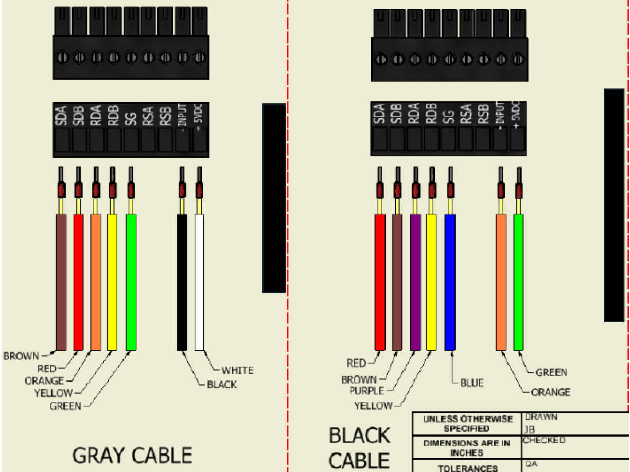
Click the link below to download the diagram in PDF format.
- Details
- Troubleshooting and Guides
COUNTING SYSTEM
The rewind machine incorporates a bi-directional dual preset counter. This permits the operator to set sepa- rate deceleration (Preset A) and stop (Preset B) points. The counter is driven by means of two magnetically operated reed switches located in the table top beneath the counter drive roll. A magnet in the lower end of the counter drive roll operates the reed switches. The combined signals from each reed switch allow the counter to automatically count up or down depending on the direction of rotation of the counter drive roll. This is primarily used when pulling defective material backwards off the rewind roll. Be sure the web is held against the counter drive roll when it is pulled backwards.
PROGRAMMING DECELERATION AND STOP POINTS
To set the final count, press the PRE B button on the counter once. In approximately two seconds the current value will be displayed. To change the value, simply press the button under the digit that you wish to change. Each time the button is pressed, the digit will increment by one. When the desired value has been set, push ENTER once to store the value into memory. To set the count at which you wish the machine to go into the deceleration mode, push PRE A and follow the same procedure as described above. If you do not wish to have a deceleration period, simply set the final count Preset B as normal and set Preset A to any number larger than Preset B.
While it is possible for the counter to become unlocked (possibly due to line noise, electrical storms, etc.), it is important to note that this will disable the counter from performing as it should. In order to correct the situation, the counter will need to be re-programmed. For your convenience, we have provided re- programming instructions located in the final section of this manual in the event that this occurs
DETERMINING PRESET B (STOP POINT)
The counter registers one count per ten inches of web travel when using the standard ten-inch circumference counter drive roll. This makes it easy to calculate the appropriate number to enter into the counter in order to wind a roll of a given number of labels. The number is calculated as follows:
𝐂𝐨𝐮𝐧𝐭 = (𝑵𝒐. 𝒐𝒇 𝒅𝒆𝒔𝒊𝒓𝒆𝒅 𝒍𝒂𝒃𝒆𝒍𝒔)(𝒓𝒆𝒑𝒆𝒂𝒕 𝒍𝒆𝒏𝒈𝒕𝒉)/𝟏𝟎
EXAMPLE: To wind a roll of 1000 labels of 3 inch repeat length, the number 300 would be entered as the final count (Preset B).
𝐂𝐨𝐮𝐧𝐭 = (𝟏𝟎𝟎𝟎)(𝟑)/𝟏𝟎 = 𝟑𝟎𝟎
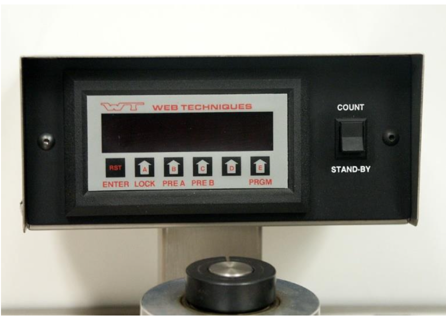
Figure 2 Counter Package
DETERMINING PRESET A (DECELERATION COUNT SETTING)
The point at which deceleration should begin depends on many factors (rewind speed, finished roll diameter, etc.). Therefore you probably will need to test your de- celeration count setting each time you rewind a new type of label. The desired technique is to have the ma- chine stop shortly after it decelerates fully and has sta- bilized at the lower speed. For the first attempt try a setting that is fifty counts less than the final count. This means that the counter will begin to decelerate the machine 50 counts before the end of the roll. EXAMPLE: If the final count (Preset B) is 300, then the deceleration count (Preset A) should be set at 250.
AUTOMATIC RESET
After winding a roll (and reaching the final preset num- ber), the counter will reset to zero automatically when the start pushbutton is pressed to start a new roll. This is the only time automatic resetting can occur. Counting will proceed normally each time the machine is stopped and started (without resetting) until Preset B has been reached. You may reset the counter to zero at any time by pushing the “RST” button on the counter.
ELECTRICAL CONTROL ADJUSTMENTS
The following list of settings has been pre-adjusted by Web Techniques, Inc. to cover most applications. If these settings are not optimal for your requirements, adjustments may be made with discretion. These set- tings are located on the printed circuit board closest to the terminal blocks on the motor control. The motor control is located inside the control cabinet.
MINIMUM SPEED
If a higher than zero minimum speed is desired, readjust the minimum speed by turning the main speed control knob on the front of the machine to zero setting (full counterclockwise position). Then adjust the trim poten- tiometer marked MIN to the desired setting.
DECELERATION RATE
If your labels become loose during the deceleration period with the web tension set at the necessary level, you should increase the deceleration rate by turning the trim potentiometer marked DECEL clockwise. If you feel that the deceleration period is too long, turn the decel- eration trim potentiometer counterclockwise to reduce the deceleration rate.
ACCELERATION RATE
Turning the trim potentiometer marked ACCEL clock- wise increases the amount of time required for the mo- tor to reach full speed. The setting should be such that the web does not break when the motor is started.
PROCEDURE FOR RE- PROGRAMMING KEP MC2A9 COUNTERS
UNLOCKING THE COUNTER
- Press LOCK. The display will show “CodE” for a few seconds.
- When “CodE” disappears, enter the code 13579 and press ENTER.
- The counter will then show “un LoC” for a few se- conds. You are now ready to reprogram the counter.
SETTING SCALE FACTORS
- Press PRGM.
- When “FACtor” appears, press ENTER.
- When “dP F A” appears, press PRGM. Then press ENTER.
- Set “dP F A” to 1 if it is not already set to 1 and press ENTER.
- When “dP F b” appears, press PRGM. Then press ENTER.
- Set “dP F b” to 1 if it is not already set to 1 and press ENTER.
- Press ENTER again.
SETTING COUNT MODE
- Press PRGM twice.
- When “Count” appears, press ENTER. Then (if necessary) press PRGM until “rSt 0” appears.
- Press ENTER.
- When “dP LoC” appears, press PRGM. Then press ENTER.
- If necessary, press PRGM until “A nEtb” appears.
- Press ENTER.
- If necessary, press PRGM until “ASub b” appears.
- Press ENTER.
- If necessary, press PRGM until “Hi CPS” appears.
- Press ENTER.
SETTING THE RELAY OPERATION
- Press PRGM 4 times (until “rELAY” appears).
- Press ENTER.
- Set “A XX.X” to “A 00.0” and press Enter.
- Set “b XX.X” to “b 00.0” and press Enter.
SETTING THE COUNTER LOCK CODE
- Press PRGM 3 times (until “LoC” appears).
- Press ENTER.
- If necessary, press PRGM until “LC Pr9” appears.
- Press ENTER.
- The display will show “CodE” for a few seconds.
- When “CodE” disappears, enter the code 13579 and press ENTER.
LOCKING THE COUNTER
- Press LOCK. The display will show “CodE” for a few seconds.
- When “CodE” disappears, enter the code 13579 and press ENTER.
- To verify that the counter is locked, press the PRGM key. The “LoC” message should appear on the counter.
- Details
- Troubleshooting and Guides
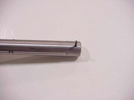
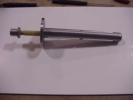
Note: Over time burrs can form on the drive shafts/coreholder shafts causing them to not sit flush with the top of the system. To remove any burrs from the drive shaft/coreholder shaft, follow the instructions below. If not removed this could cause the coreholder to get stuck in the system.
1) Use a .625” reamer to ream out the internal portion of the shaft. Do not use a drill, clamp a set of vice grips onto the shaft of the reamer.
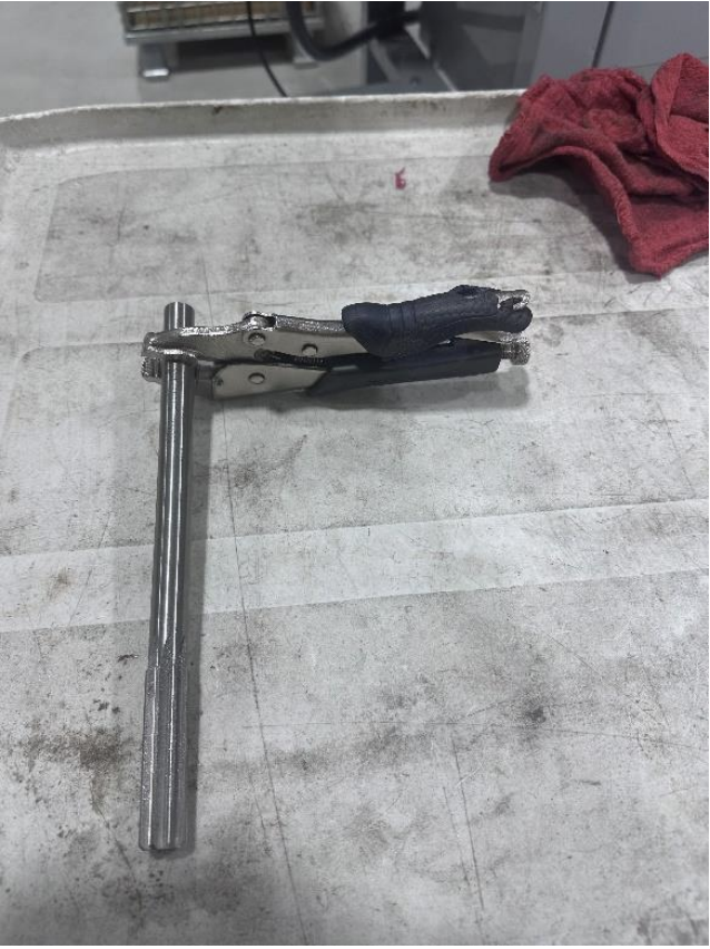
2) Turn reamer by hand until reamer has bottomed out on the internal pin (approximately 2.25” down). Remove reamer and use compressed air to blow the debris out.
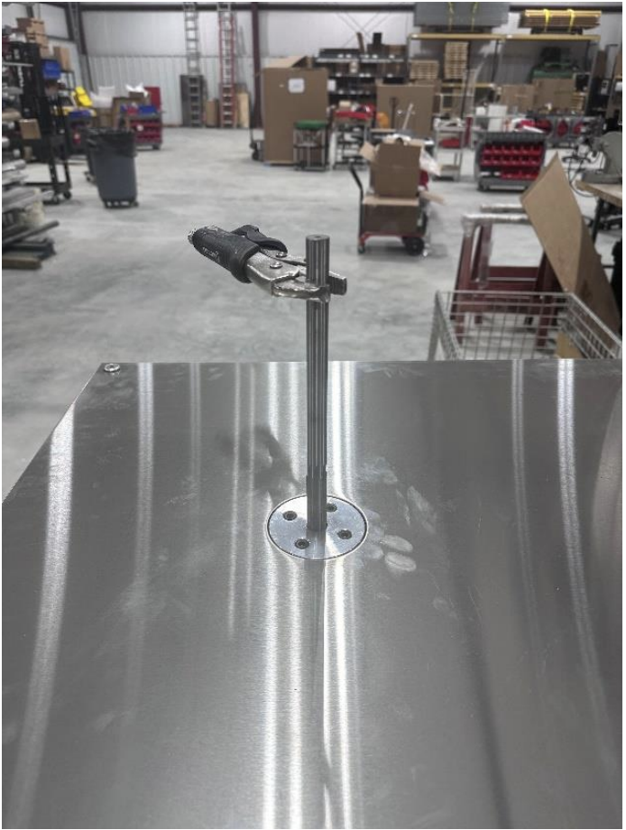
3) Next remove burrs from the coreholder shaft. Using a file, file around the edges on the bottom of the shaft (there should not be any sharp edges).
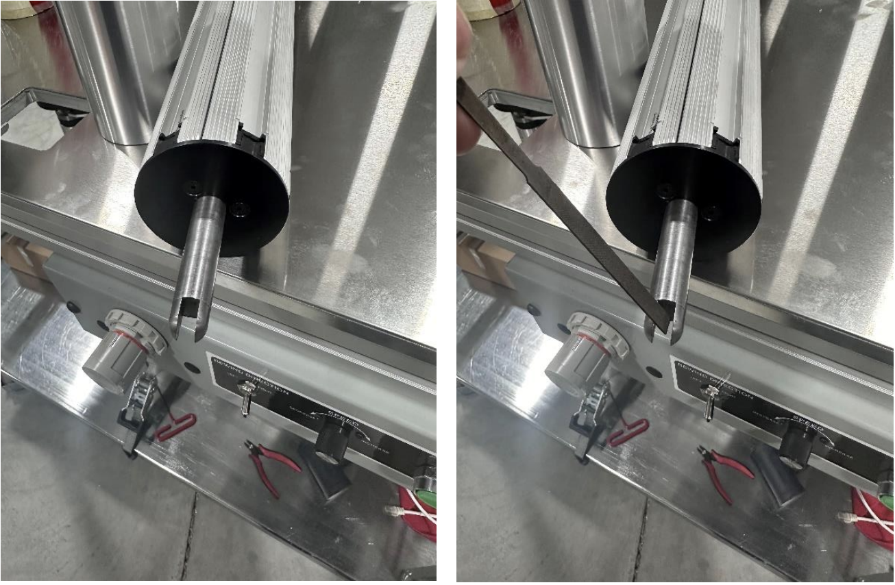
4) Place coreholder into system, if coreholder does not sit flush repeat the steps above.
To download the procedure for removing burrs from WT-30 and WT-35 drive shafts, click the link below.
- Details
- Troubleshooting and Guides
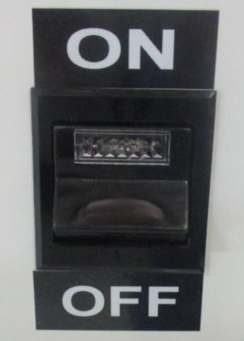
STEP 1: ENSURE SYSTEM MAIN POWER SWITCH IS IN THE OFF POSITION AND/OR UNPLUGGED BEFORE
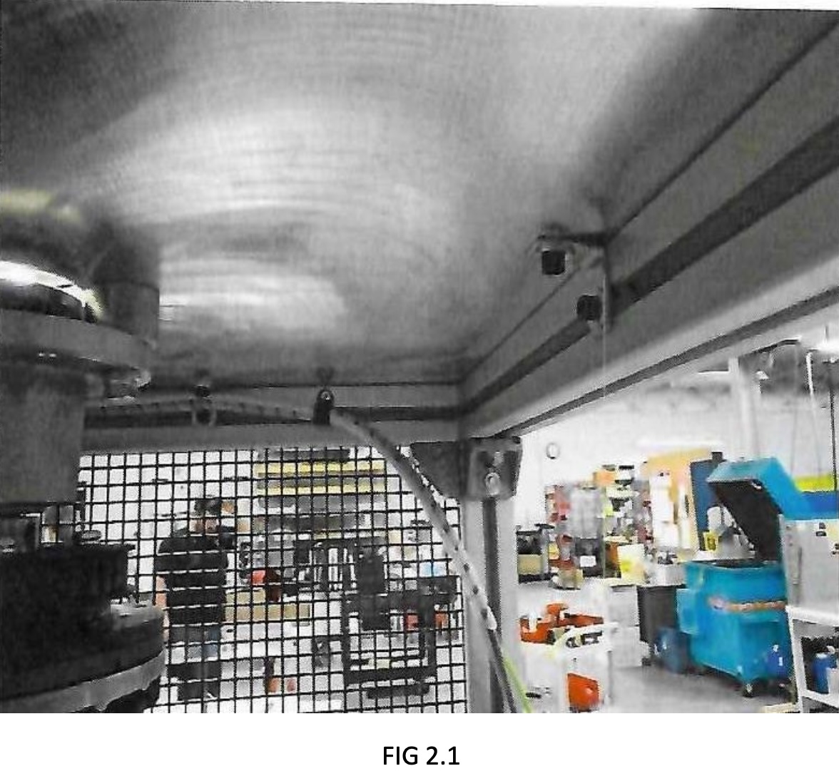
STEP 2: SECURING TOP TO FRAME
2-A) Secure angle brackets to top(FIG. 2.1). Use (5) ¼-20 X 5/8” SHCS (C1M5/6302505) and ¼” washer (C1C1/6612500). Hand tighten SHCS to top to make sure top is in correct position. After all are hand tightened, tighten to frame first, then top(FIG. 2.1).
STEP 3: ADUSTING PULLEYS AND BELTS
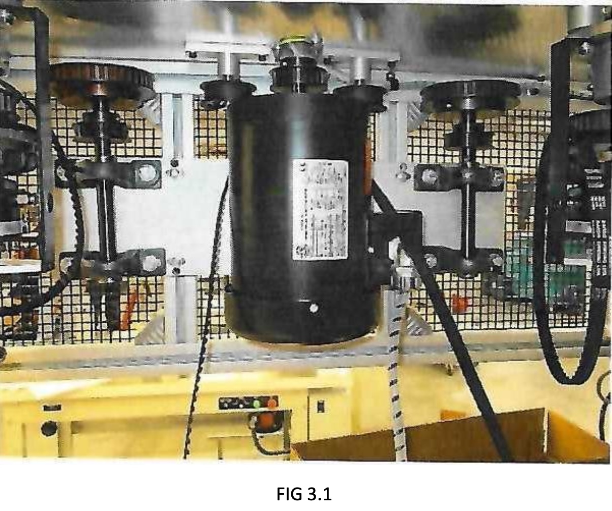
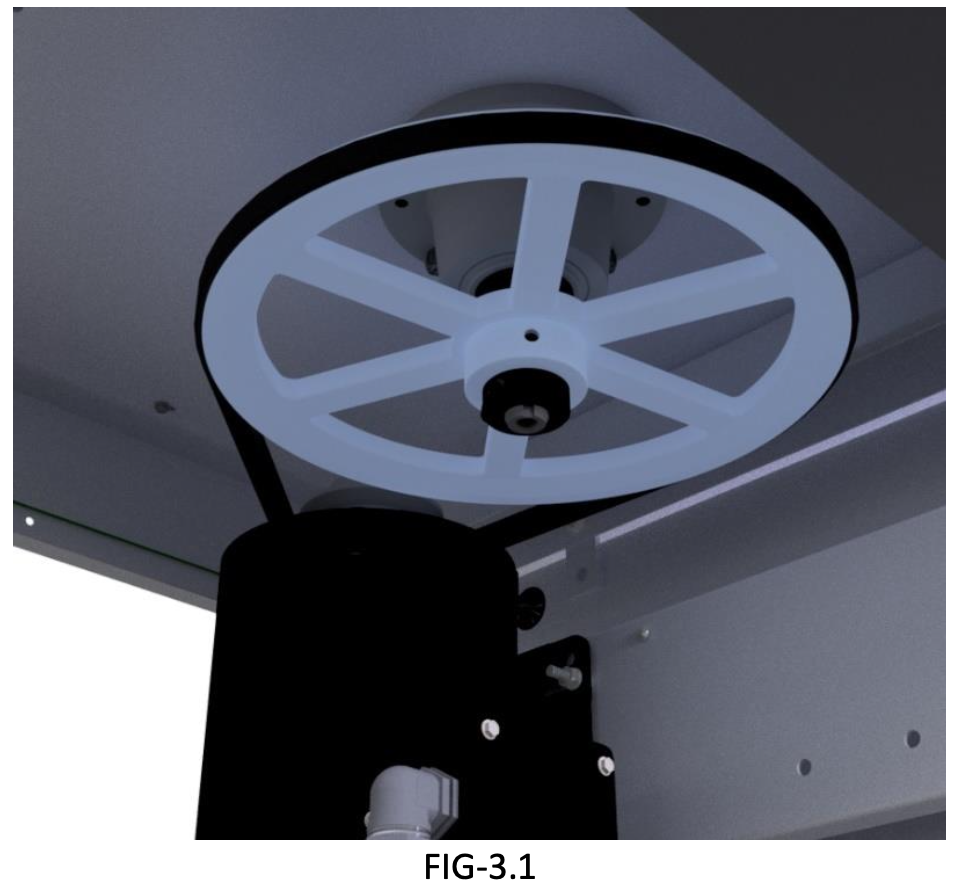
3-A) Place ½” timing belt (C2 side/90-9318) over motor (FIG 3.1).
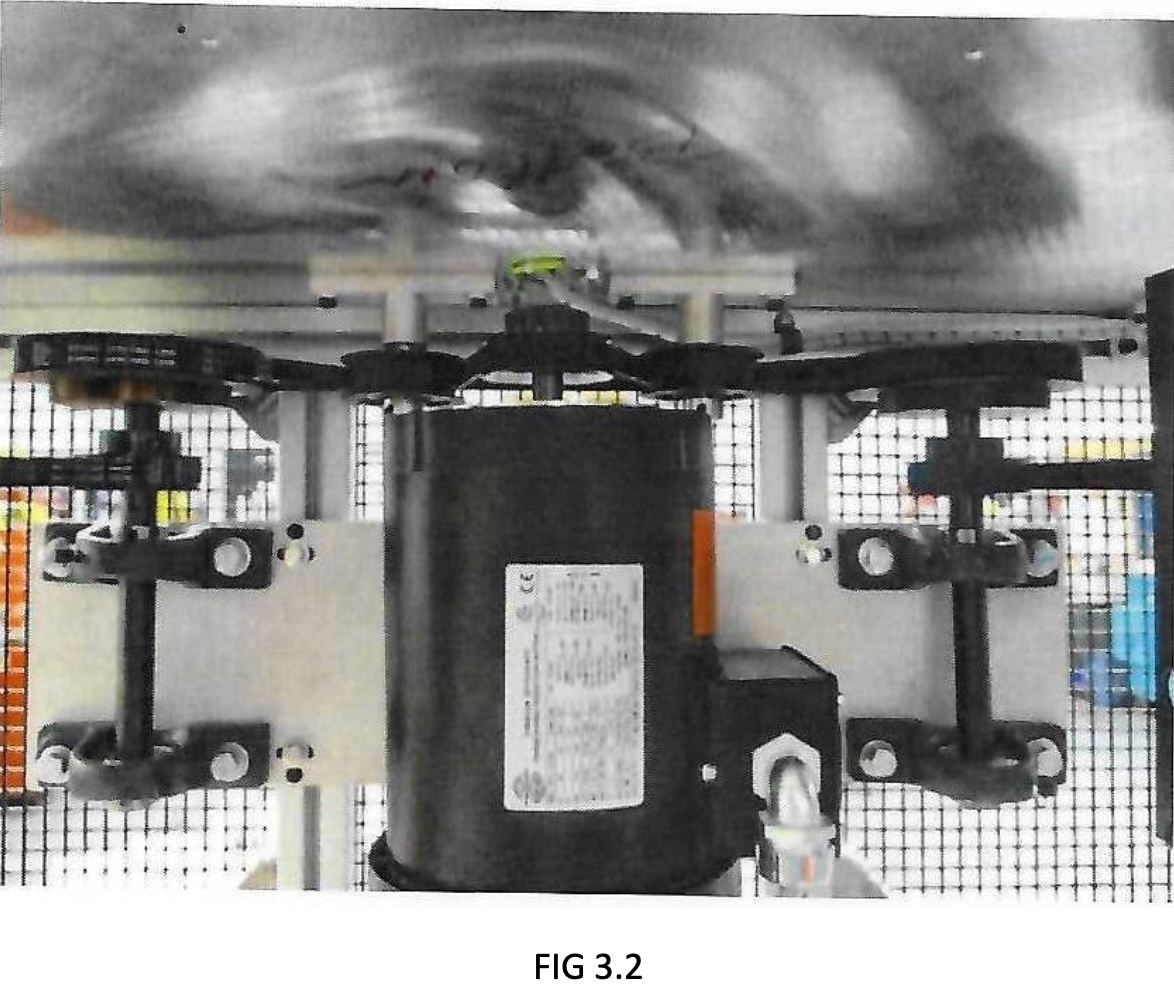
3-B) Place belts on pulleys (FIG 3.2).
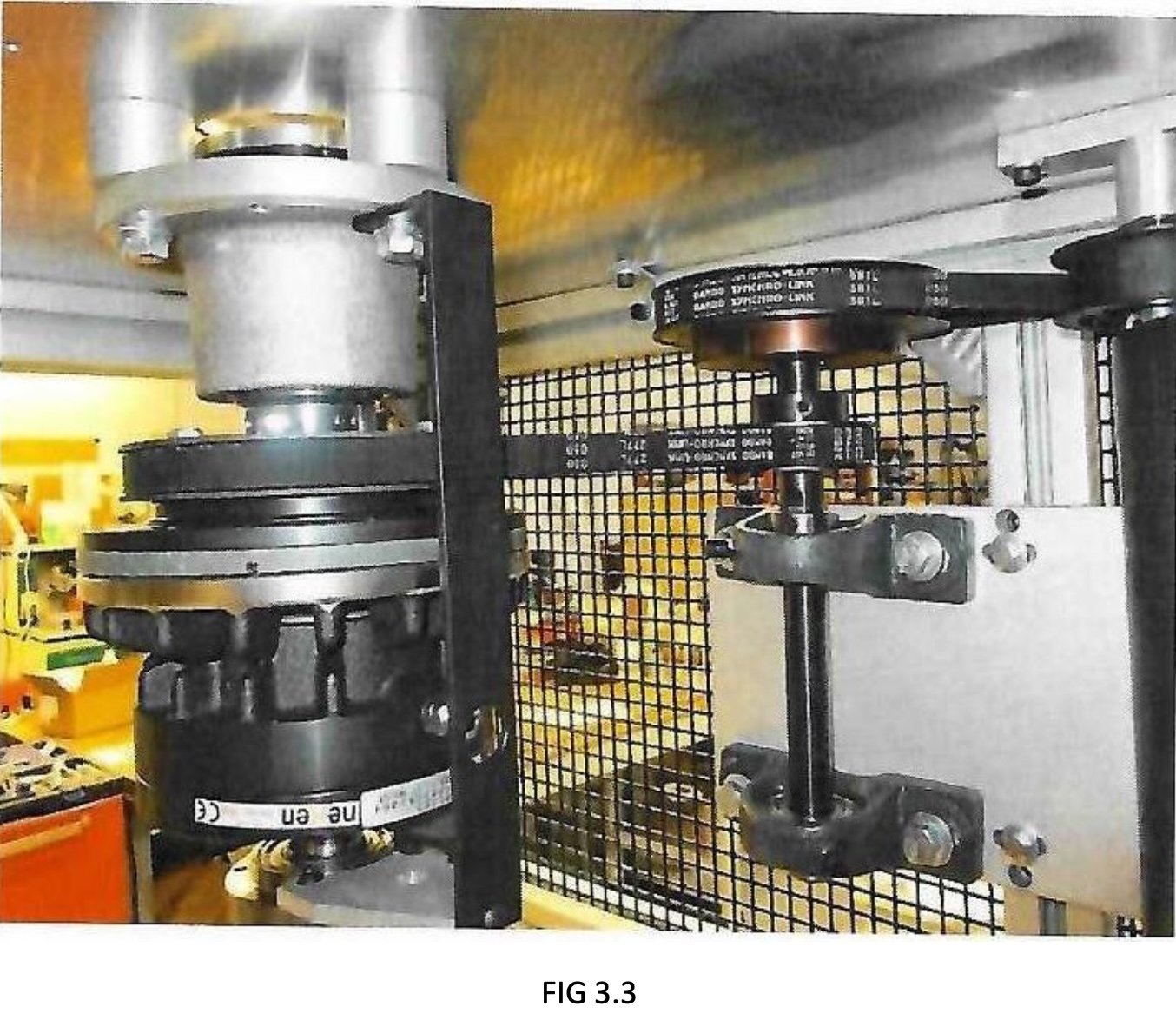
3-C) Adjust small belts on shaft assembly to where belts have approximately ½” give, then tightening bolts on pillow bearing blocks (FIG 3.3).
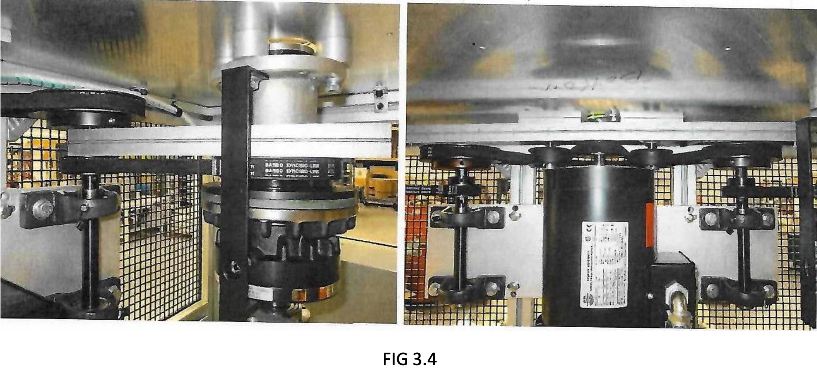
3-D) Use straight edge to make sure pulleys are even with each other and pulleys are parallel to top.
Double check screws on shaft assembly are tight (FIG 3.4).
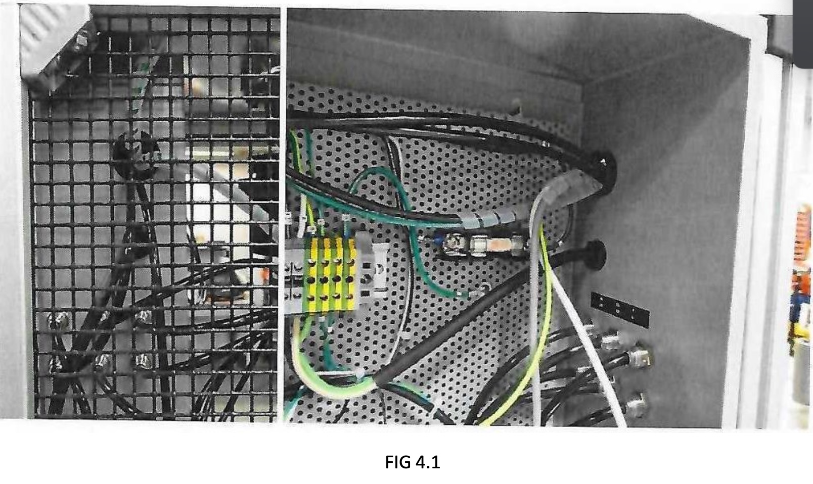
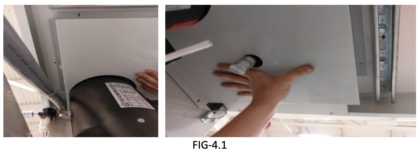
STEP 4: POSITIONING ENCLOSURE AND FEEDING CABLES INTO ENCLOSURE
4-A) Feed COM cable, scanner cable, ground wire, and motor power cables through top hole of enclosure (FIG 4.1)
- Details
- Troubleshooting and Guides
System Drive Belt Removal and Installation Procedure.
NOTE: BE SURE POWER IS OFF AND SYSTEM IS UPLUGGED FROM POWER SOURCE.
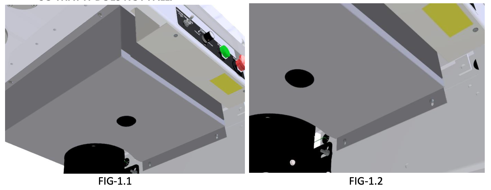
STEP 1: Remove belt guard from bottom of WT-26 system by removing (3) 8-32 x 1/2" screws (FIG-1.1) on the bottom of the systems top and (2) STPH #8 x 3/4” screws from the motor mounting plate (FIG-1.2).
CAUTION: WHEN REMOVING BELT GUARD BE SURE TO HOLD IN PLACE WITH HAND SO THAT IT DOES NOT FALL.
STEP 2: Loosen motor mounts and push motor towards larger pulley. If belt will not come off, motor will need to be removed completely. To remove motor, loosen and remove all four nuts and lock washers from mounting studs.
CAUTION: MOTOR IS HEAVY DO NOT DROP WHILE REMOVING FROM STUDS.
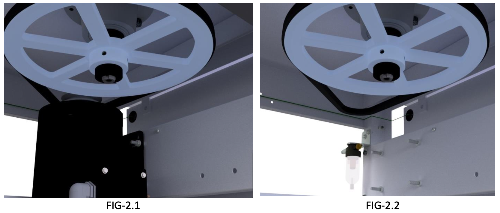
STEP 3: Place belt around both pulleys and place motor back on motor mounting studs (FIG-3.1). Screw nuts back on studs but do not tighten down with appropriate hardware. Push motor away from big pulley to tighten belt then tighten motor in place.
CAUTION: DO NOT OVER TIGHTEN BELT, BELT SHOULD HAVE A 1⁄2” OF PLAY WHEN PRESSING ON THE MIDDLE OF BELT.
STEP 4: Install the belt guard (19-1240-1) using (3) 8-32 x1/2” hex-washer head screws, and (2) pan head screws. Use the hex-washer head screws for wooden holes and pan head screws for holes into frame (FIG-4.1).
- Details
- Troubleshooting and Guides
This is an attempt to explain the trim pot settings in a KB Motor Control.
- Decel - Adjusts deceleration time to go from full speed to stop (Ramp-Down Time).
(Average Setting – 10:00 to 10:30 o'clock). - Accel - Adjusts acceleration time to go from stop to full speed (Ramp-Up Time).
(Average Setting - 1:00 o'clock). - Max - Adjust the maximum amount of voltage allowed for the motor control to send to the motor.
(Average - 1:00 o'clock) - Min - This is the pot to set first. Make sure main speed pot is set to zero. With machine in stop mode, this gets turned up until the motor starts turning and then turned down until the motor stops turning with no noise.
(Average Setting - 9:30 o'clock) - CL (Current Limit) - Adjusts the maximum amps that goes into the motor control. This setting serves to protect the motor and control against overloads. (Average Setting – 12:30 to 1:00 o'clock)
- IR Comp - this stabilizes the motor control to prevent surging, compensates for variation in amps to the motor control and voltage out to the motor. Designed to improve load regulation for varying changes in load on the motor, provides minimal speed changes as load changes. NOTE: This gets turned all the way down for Constant Speed Control machines.
(Average Setting - 9:30 to 10:00 o'clock) (for constant speed machines, turn all the way down to zero). - Jog - Use the factory setting of 5:00 o'clock (when control is in upright position)
These settings are adjusted at the factory and tuned to provide optimal output and service.
- Details
- Troubleshooting and Guides
SAFETY WARNING: BEFORE PERFORMING ANY REPAIR TO WEB TECHNIQUES EQUIPMENT, YOU MUST TURN OFF THE POWER AND DISCONNECT THE EQUIPMENT FROM THE POWER SOURCE.
KBCC-125R Motor Control 115V (3/4 or 1 HP)
There are two tests that can be performed separately to test the motor control: Main Speed Pot Test and Direction Switch Test. But first, check to ensure that all the fuses on both the machine and the motor control are good before proceeding. These two tests can also be used determine if the main speed pot and/or the direction switch is at fault. For either test, the customer will need to create a short jumper wire approximately 6 inches long to use to jumper two terminals together. Be sure to power off the machine and unplug from power source. When running these tests, remove all label materials and rolls from the machine. You should also check to make sure that the ice cube relays (K1, K2 and K3) are secure in their sockets and operating properly.
Main Speed Pot Test
- Power off machine and unplug from power source.
- Unhook wires P1, P2, P3. (Important: Make sure the wires you are removing do not touch ground or each other).
- Place jumper wire between P2 and P3.
- Plug machine back into power source, and turn power switch on.
- USE CAUTION (Because the machine could run at full speed): Press start button and the machine should run at full speed. (NOTE: Main speed pot will not function during this test) If the machine does not run full speed, then it is a bad motor control, replace motor control. Side Note: If the machine did run at full speed, this could mean that the main speed pot is bad, replace main speed pot.
- Power down the machine and unplug from power source. Remove jumper wire & re-attach wire 67 to P1; wire 73 to P2; wire 69 to P3.
Direction Switch Test
- Power off machine and unplug from power source.
- Unhook wires S1, S2, S3 located at bottom right of motor control. (Important: Make sure the wires you are removing do not touch ground or each other).
- Place jumper wire between S1 and S2.
- Plug machine back into power source, and USE CAUTION because the machine should start as soon as you turn power switch on. If the machine did not start as soon as you turned the power switch on, then it could be a bad motor control but make sure to check the K1 relay to see if it is working properly, if it is then replace motor control. Side Note: If the machine did run as soon as you turned the power switch on, this could also mean that the direction switch is bad, replace direction switch.
- To test for the opposite direction. Power down the machine and unplug from power source. Remove jumper wire from S1 and hook it to S3 (this will cause the machine run in the opposite direction).
- Plug machine back into power source, and USE CAUTION because the machine should start in the opposite direction as soon as you turn power switch on.
- Power down the machine and unplug from power source. Remove jumper wire & re-attach wire 78 to S1; wire 75 to S2; wire 77 to S3.
Motor Trim Pot Settings
(Note 1: these are not absolute values, more like guidelines to get them back to running)
(Note 2: Adjust these by turning counter-clockwise if past 12 o’clock or turning clockwise if before 12 o’clock)
- DECEL 10 to 10:30 o’clock
- ACCEL 1 o’clock
- MAX 1 o’clock
- MIN 9:30 o’clock
- CL 12:30 to 1 o’clock
- IR 9:30 to 10 o’clock
- JOG 5 o’clock
- Details
- Troubleshooting and Guides
SAFETY WARNING: BEFORE PERFORMING ANY REPAIR TO WEB TECHNIQUES EQUIPMENT, YOU MUST TURN OFF THE POWER AND DISCONNECT THE EQUIPMENT FROM THE POWER SOURCE.
WT-25 Counter Circuit Board LED’s Not Lit
- Condition: The counter has power (at zero), but the LEDs do not light up on the counter circuit board. Nothing happens when you spin the Counter Drive Roll. Does not count. FIRST, (hear me out on this): Remove the counter circuit board from the counter and the machine and re-install it back on the counter and the machine. Reason is that there could be a corrosion causes poor connections, and by simply removing and reinstalling the counter circuit board can break up some of that corrosion. You would not necessarily be able to see the corrosion.
- Possible causes:
- Bad capacitors on the counter circuit board, replace counter circuit board.
- Bad counter, since the counter supplies the power for the LEDs on the counter circuit board, replace counter.
- Severed connection between the reed switches and the counter/counter circuit board, test wiring harness.
- Corroded terminals, Switches are stuck (polymerized)
- Possible remedies:
- Remove and reinstall the counter circuit board, (it’s crazy, I know, but sometimes it works—connection issues)
- Replace counter, counter circuit board and/or reed switches (probably should replace the reed switches anyway, if older).
- Replace wiring harness from switches to counter circuit board
* Always use “dark energize”, only use light if you are counting a perforated hole.
- Details
- Troubleshooting and Guides
SAFETY WARNING: BEFORE PERFORMING ANY REPAIR TO WEB TECHNIQUES EQUIPMENT, YOU MUST TURN OFF THE POWER AND DISCONNECT THE EQUIPMENT FROM THE POWER SOURCE.
Reed Switch Failures
- On older WT-25 machines, when the reed switches may begin to fail, the customer more than likely needs to replace the old counter circuit board along with the reed switches. This may be due to the old board causing the reed switches to fail. The older board can weaken over time and excessive use, which can result in less voltage output for the switches which in turn could polymerize the tips of the reed switches and cause them to stick. The newest revision circuit board has a higher voltage and can help prevent this condition. The customer needs to replace their old style board because it is wearing out. "It is not a defect, but a wear issue.”
- Check the connectors to make sure they are tight and that the wires have not been pulled loose inside the connector.
Reed Switch Troubleshooting
- When troubleshooting a reed switch for length counting, one way to check it on the WT-25 is by locating the pair of LED Lights on the counter circuit board, DS1 and DS2. These are always on except when the magnet on the bottom of the Counter Drive Roll passes over the corresponding switch. The two led lights are always on except when the magnet on the bottom of the counter drive is over the top of the reed switches in the table.
- The counting direction is determined by which light comes on first after both of them are off. There has to be a period where both lights are off in either sequence (or direction) in order for the process to operate successfully.
- Details
- Troubleshooting and Guides
SAFETY WARNING: BEFORE PERFORMING ANY REPAIR TO WEB TECHNIQUES EQUIPMENT, YOU MUST TURN OFF THE POWER AND DISCONNECT THE EQUIPMENT FROM THE POWER SOURCE.
Machine Hits Preset A, Then Stops and Starts Again
- Need to adjust the "decel" pot on the motor control to be in the approximate range of the 10 o'clock position.
Machine Runs Wide-Open
- Is the main speed pot turned all the way up to maximum?
- Could be a bad main speed pot.
- Does the machine have a constant speed control? and is it turned on? and is it set to a high number?
- If the machine runs full speed and you can't control the speed, it is possibly a blown SCR on the motor control, then you would replace the motor control--they are not repairable--KB does not sell parts for them. Caution Warning, you need to find out what may have caused the motor control to fail in the first place. If you sell them a new motor control and they install it without repairing the problem that caused the first one to fail, it could blow the new motor control. Make them know that if they install it, they own it and they are responsible for testing to determine and repair the initial problem that caused the motor control to fail in the first place.
Machine Slows Down While Running
- Make sure that the machine didn't just hit Preset A, and is now running in idle mode (Can you adjust the speed with the idle speed pot?).
- Drive Belt Slipping, replace worn belt
- Check the Ice Cube relays on the main circuit to make sure they are pushed in all the way. Remove and replace the relays several times to make sure you are getting a good connection.
- Check for a loose connection on the back of the direction switch on the front panel, or replace the switch altogether.
- Could have a faulty main speed potentiometer; replace it with a new one (best to replace this pot & direction switch at the same time).
- Could be a bad reverser on the motor control, if so replace motor control (See Motor Control Testing).
Machine Won’t Run Full Speed
- Make sure that the machine isn’t just in idle mode. This is where the machine reaches Preset A (slowdown count) and idles until it reaches Preset B (stop count). See if they can adjust the speed with the idle speed pot, if so, check the presets.
- Bad Main Speed Pot
- Bad Direction Switch.
- Possibly they need to re-program the counter.
- Check to make sure the drive belt isn't worn and is slipping.
Machine Surges at Slow Speed
- The machine is surging at slow speeds because of the motor control trim pot called IR Comp.
- Use a very small Phillips head screwdriver, then locate and turn the IR Compensation potentiometer counterclockwise to stabilize the drive (prevent surging). Theoretically, turning the dial position to about a 9 to 10 o’clock setting should cure the surging problem, this is the typical setting we arrive at when we are testing the motor controls.
Machine Surges with Constant Speed Control On
Constant Speed Control Surges or is Erratic (OTHER THAN RUNNING TOO SLOW) For Constant Speed Controls PRIOR TO MAY, 2013 ONLY
- There is a possibility that this condition is caused by a bad reed switch that drives the constant speed control. On constant speed control machines prior to May, 2013, the constant speed control is driven by two reed switches 180 degrees apart underneath the counter drive roll. Now mind you there will also be two other switches that is used for length counting. The constant speed control switches are the ones two outer ones 180 degrees apart. The length counter switches are the two closest together.
- The symptom is that the constant speed control speeds up and slows down. This can be a slight change or up to mildly drastic. During this time the constant speed control never really reaches a constant speed and is like "hunting" for the correct target speed.
- The reasoning behind this is that perhaps is a "weak" reed switch that bounces a lot when the magnet comes near and engages it, but it continues to bounce. Bounce is when the switch goes to engage and it bounces against the contact creating and on-off-on-off situation.
- Diagnostic Tool: Unplug one of the switches and see if the constant speed control smoothes out. If not, re-plug that switch back on and un-plug the other one. If the second switch smoothes it out, then replace the first one or vice versa as the case may be.
- Recommendation: Replace both Reed Switches; always replace reed switches in pairs.
Machine Won’t Start
- Preset B has been reached, press stop button, reset counter
- Bad Main Speed Pot.
- Ice Cube Relays have wiggled out of their sockets, push them back in.
- Blown Fuses
- Loose connections/Break in the wiring
- Bad Direction Switch
- Jumpers on the main circuit board need checked to make sure they are not losing connection
- Motor Control is bad, perform motor control speed pot test and direction switch test
- Motor brushes have failed, replace brushes or replace motor.
Main Speed Pot is at Zero, Machine Still Moves
- Need to adjust the MIN Trim pot on the motor control, by turning it counterclockwise until the motor stops turning and “is quiet”.
Motor Starts Slow, Perhaps Needs Help to Start
- This indicates worn DC motor brushes, and the brushes may need replaced. However, this also indicates a worn armature. If new brushes do not cure the problem, replace the motor.
- Possible worn drive belt, check and replace if necessary.
- Need to adjust the ACCEL Trim pot on the motor control, by turning it counterclockwise until approximately 12:30 to 1 o’clock.
Main Speed Pot Won’t Slow Machine Down
- Is the machine in idle mode? If so, the main speed pot does not operate during idle mode, or only the idle speed pot.
- Switch to standby next to counter, if main speed pot doesn’t operate, replace the pot.
Stop Relay Engages
- The machine won't run, and the stop relay engages, then ask them if Preset B is set to zero. Preset B tells the machine to stop. If Preset B is set to zero then the machine won't run. It is possible the machine thinks it has reached the stop signal.
Machine Won’t Stop at Presets
If the machine won't stop at the presets, meaning it just keeps on running, a few things to check:
- First, make sure the Count/Bypass switch next to the counter is not on "Bypass Preset".
- Check the K2 Stop Relay to make sure it is plugged in all the way (remove and plug-in a couple of times). (If the machine does not go into idle mode, check the K3 decel relay make sure it is okay too).
- Make sure that the counter is respectively past these two presets in order to make them work for this next test.
If there is 115v between (Preset B output on back of counter) J2-2 and (Ground) J2-4, then preset A is good. If no idle mode then check for 115v between (Preset A output on back of counter) J2-3 and (Ground) J2-4. If both of these are good then check the wiring between K2 and K3 relays to see if there is a break. Or perhaps a bad K2 and/or K3 relay(s). - Check the programming in the counter. If unable to correct the programming, then replace the counter.
- You can send along a new counter circuit board with the new counter for troubleshooting purposes. Sometimes customers may decide to keep the new one in order to have a spare. Remind customers that these repair ideas are not absolutes, but trial and error method.
Machine Only Runs One Direction
- Direction Switch needs replacing? Check to make sure that one of the wires has came off the back of the switch.
- Motor Control has a bad SCR (reversing module), if so, replace motor control (See Motor Control Testing).
Machine is Stuck in Idle Mode
- Relays in the counter could be stuck, replace counter.
- K3 Decel Relay is bad or loose or missing, (you can test this be swapping it with the K2 stop relay-they are the same relay)
- Bad Connection in the wiring harness from counter circuit board to main circuit board.
Machine Won’t Stop
- Possibly it is a bad motor control
- If you flip the direction switch while the machine is running, does it change directions, if not, possibly bad motor control or direction switch.
Machine Only Runs When Pressing (and holding) Green Start Button
- Chances are the K1 Relay has wiggled out of its socket enough to lose contact. Check the relays to make sure they are pushed in all the way. Check that wires are properly connected on the back of the Green pushbutton switch and on the main circuit board.
- Possibly wire #9 in the plug to the right of the K1 Run Relay may have lost connection. This wire runs from the green start button through the stop button to the connector next to the K1 relay on the main circuit board.
- Details
- Troubleshooting and Guides
SAFETY WARNING: BEFORE PERFORMING ANY REPAIR TO WEB TECHNIQUES EQUIPMENT, YOU MUST TURN OFF THE POWER AND DISCONNECT THE EQUIPMENT FROM THE POWER SOURCE.
The WT-25 Label Rewinding Machine has a ‘count by length’ counting system. This system consists of a counter, a counter circuit board (which plugs into the rear of the counter), a Counter Drive Roll (this has one magnet in the bottom), and two magnetic proximity switches called reed switches that are mounted in the tabletop surface itself just underneath the counter drive roll. The circumference of the standard counter drive roll is 10” (12” or Metric 10cm counter drive rolls are also available). Each revolution of the standard counter drive roll represents 10” of web travel and increments the counter by one.
Parts for a WT-25 Series Counting System include:
- Counter 85-1302 for WT-25 or 26-1175 for WT-25LC & WT-25LCI
- Counter Circuit Board 01-1113 for WT-25 or 01-1107 for WT-25LC & WT-25LCI
- Reed Switches (2) 26-1101 (all models)
- Wiring Harness from Counter Circuit Board to Reed Switches 26-1102
- Wiring Harness from Counter Circuit Board to Main Circuit Board 26-1132
Counter does not light up
- Check if the LED lights on the counter circuit board are lit. If not, then the counter may need replacing.
- Check for 115v power to terminals 11 & 12 at the back of the counter (not at back of the circuit board). If there is 115v to the back of the counter at terminals 11, then replace the counter. If there is no power at terminals 11 & 12, then check for a blown fuse, a broken wire in the wiring harness, whether the machine’s power switch is on, or is there a power outage at the receptacle where the machine is plugged.
Counter Won’t reset to Zero when pressing green stop button after reaching stop count (Length Mode Only)
- Check the ice cube relays to make sure they are seated properly with good connection
- Replace Counter to see if that cures the issue, if not then, replace counter circuit board.
- If neither new counter or new counter circuit board does not cure problem, check wiring behind green start button or replace button.
- Check Wire #21 for broken wire bad connection.
Counter Just Skips Counting
- This could be due to a number of factors alone or all of them at once. Remove the counter drive roll by loosening the lock collar and removing the roll. There are two magnetic proximity switches (Reed Switches) that sense when the magnet in the bottom of the counter drive roll is near. Check for debris build-up on top of these switches. Also check to make sure that these switches have not been pushed too far down from the tabletop surface. The top of these switches should reside near the surface of the stainless steel top.
- Check to see if there is a locking collar properly install on the top of the counter drive roll. If not, as the web is moving this could cause the counter drive roll to be riding up and pulling the magnet away from the reed witches. Replace the locking collar and fiber washers.
- Intermittent connection between the reed switches and the counter circuit board, check to make sure the connectors are all fastened correctly and check that the Molex pins in the connectors have not pulled back (caused by pulling on the wires instead of the connector to disconnect).
- Counter circuit board make be failing, IC chip on this board make be at fault or the entire board needs replacing.
Counter Randomly Resets to Zero
- First check the programming in the counter by following the counter re-programming instructions in the operator’s manual (we can e-mail these instructions if necessary). Check for intermittent or loose connections on the back of the counter and in the wiring harness Molex connectors. Check for smashed pins on the counter circuit board caused by over tightening screws at the rear of the counter, replace counter circuit board.
- Check the receptacle where the machine is plugged to make sure that the ground is working properly. Make sure all ground wires on the machine are connected and making good contact. Static build-up and discharge can cause a counter to react intermittently.
- SEE Counter Re-Programming. After checking the programming in the counter, if there is no problem detected, and the above steps have been followed, and then consider replacing the counter.
Counter Loses Presets
- If the counter is randomly losing its presets, this could be a symptom that the counter is ready for replacement or it could be caused by chronic static build-up and discharge. Re-program the counter, if unsuccessful, replace the counter and take static precautions.
- Perform static countermeasures, tinsel, ionization bars or anti-static sprays to alleviate future static build-up.
Machine Counts Backwards
- If the proper recommended webpath for this machine is being used, then swap the two connectors connecting wires on the two reed switches. The wires for the reed switches protrude from holes in the table underneath the counter drive roll. Each reed switch has two wires that go to a connector. The connector then plugs into another connector on the wiring harness leading to the counter circuit board. By switching these connectors, you change the direction of the count.
Counter Re-Programming
- The counter re-programming instructions are located in the rear of the instructional portion of the manual.
- Best advice for checking the programming is to:
- Take it slow;
- Do this when you will not be interrupted (important);
- Ensure what it says on the paper is what it says on the counter because the letter and number digit combinations used can look deceiving;
- Ensure the counter is locked before you begin using the machine. There is a lock code included to unlock the program and lock the program back. Go through each step slowly, stopping to double check yourself at each step. Making sure the counter program is locked when finished can be accomplished by pressing the program key and “LOC” should appear.
Counter Won’t Count
- Check Reed switches are working by looking on the counter circuit at the DS1 and DS2 led lights. If those are working properly, then check the programming in the counter. If inside the program of the counter is registering all FFFFF's in some locations of the program, this a counter fault that is an internal counter problem that is the typical result of dirty power issues, power surges, spikes, brown outs or chronic static electricity build-up and chronic bad grounding issues. These counters can recover from power issues, but over time the damage becomes cumulative until they cannot recover anymore. Need a new counter.
- Counter Circuit Board has gone bad and not interfacing the count to the counter from the reed switches. Replace counter circuit board.
- Details
- Troubleshooting and Guides
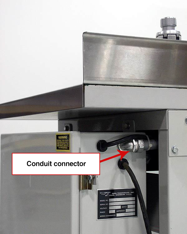
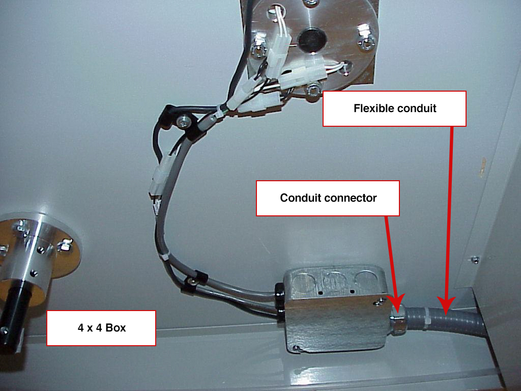
- Check the tightness of the large nuts at each end of the flexible conduit that goes from the back of the main control cabinet to the 4 x 4 box on the underside of the table top (below the counter pedestal). Also check the tightness of the conduit connector in the main control cabinet and in the 4 x 4 box.
- See if this green and yellow terminal block is mounted tightly on the track. The screw in the middle of the block is the one that clamps the block to the track.
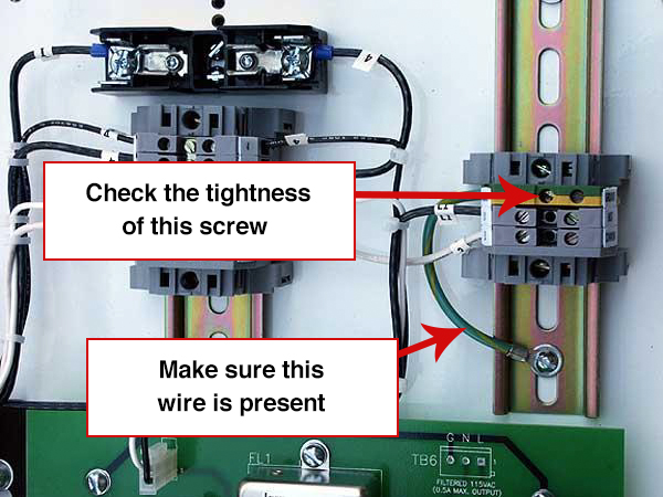 There should be a green wire from the left side of the “GND” terminal that attaches to the terminal block mounting track.
 - On later machines, there is a green ground wire attached to the terminal block mounting track that goes from that point, thru the conduit, thru the 4 x 4 box on the bottom of the table top, up through the counter pedestal, and to the ground terminal inside the counter enclosure (the terminal that the counter circuit board ground wire attaches to. We can supply this wire if you want us to do so. It will assure that the counter and table top remain securely grounded in the event that the metal conduit connectors become loose.
- Details
- Troubleshooting and Guides
Due to the exceptional design of the WT-25 series rewind machines, no regular maintenance schedule is to be followed. The items most frequently asked about are:
- Bearings: Web Techniques uses "sealed" bearings which require no lubrication.
- Motor: Brush replacement may be required, however, there is no specific time at which this replacement should occur. The life expectancy of the original brushes will vary and it may never be necessary to replace them.
- Drive Belt: There is no lubrication required.
- Brake Band Belt: Excessive unwind tension may cause the brake band belt to become dry resulting in a "squeaking" sound to occur when the machine is in operation. If this should happen, loosen the unwind tension knob enough to release the brake band belt. Moisten the belt with a light motor oil and position back in place.
- For machines equipped with lift-off cam-lock coreholders, the coreholder shaft should be kept clean and rust free. Wiping the shafts periodically with WD-40 or similar product should help prevent sticking or seizing of shafts when removing or inserting the coreholder into the table.
- Calibration (Individual Label Counting Models Only): The photoelectric counting system will need to be adjusted for each application; therefore, calibration is not required. Please refer to the supplemental instruction sheet for recommended validation procedure.
- The most important step in maintaining the performance of your Web Techniques rewind machine is regular cleaning and removal of all debris (i.e., dust, grime, adhesive, labels, tape, etc.) that can build up on the table top surface.
All coreholders, idler roll(s) and counter drive rolls should be removed from the table and the table top surface thoroughly cleaned with a non-silicone spray (we strongly recommend the use of "Pledge" by Johnson & Son, Inc.). This aids in maintaining the lubricity of the stainless steel as well as ensures all rollers will move freely while the machine is in operation.
NOTE: Idler rolls and the counter drive roll must be placed back on the table in their original positions. Failure to do so may result in length counting and/or tracking problems.
- Details
- Troubleshooting and Guides
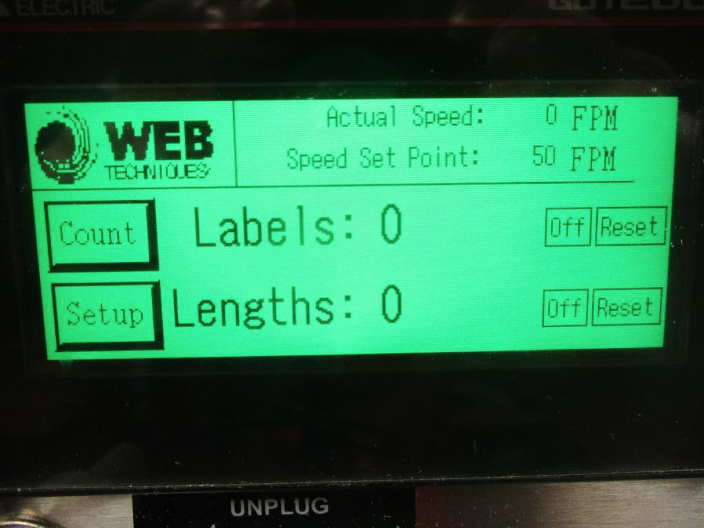
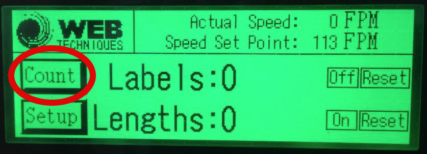
- To get to your Bypass Presets settings, first press “Count”
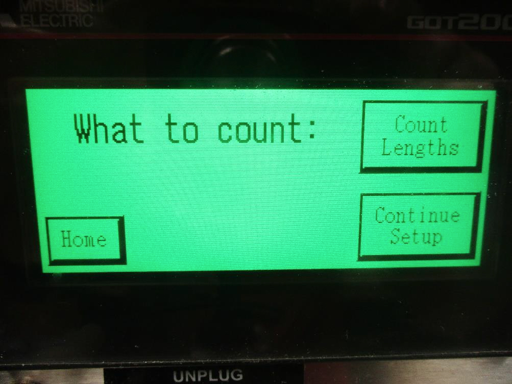
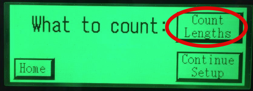
- Next, press “Continue Setup”
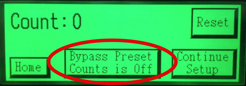
- If you are setting Preset A and Preset B amounts, make sure “Bypass Presets is turned OFF”
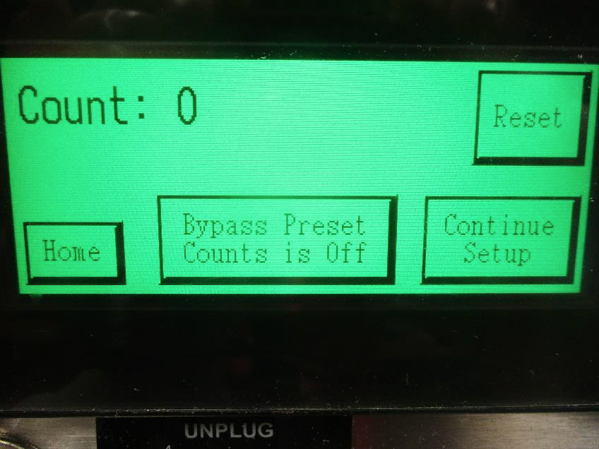
- If you are not setting Preset A and Preset B amounts, make sure “Bypass Presets is turned ON”
- Details
- Troubleshooting and Guides
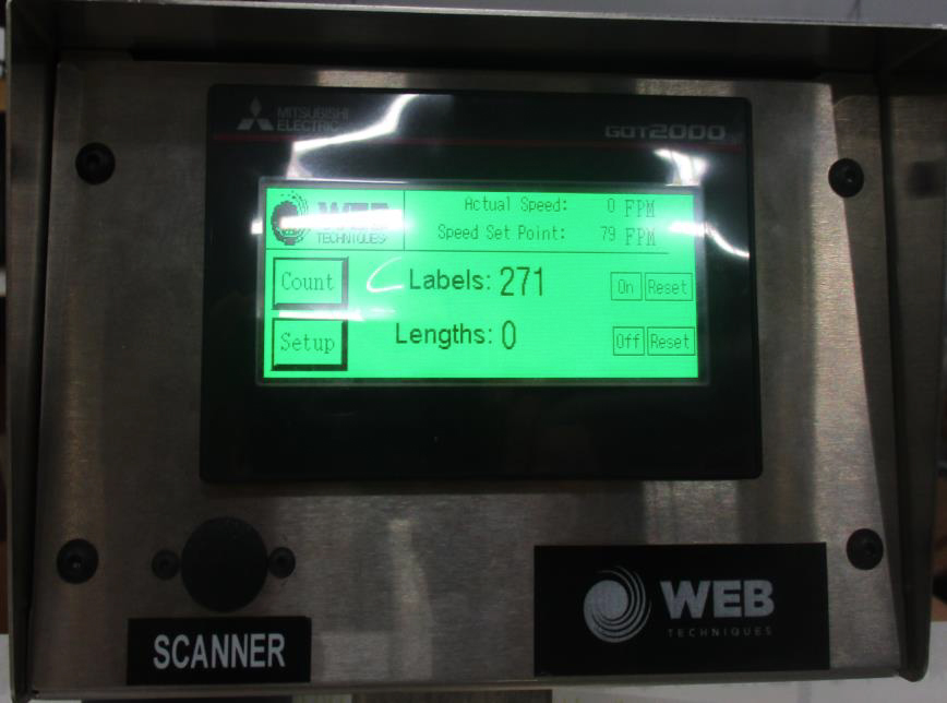
- Home Screen. Press Count button.
- Count Screen. Verify system is in Count Lengths mode and not Count Labels mode. Then press Continue Setup button.
- Once you have verified the system is in Count Lengths mode, verify that the system is in Bypass Preset Counts is Off.
- Now set your Preset A and Preset B. Run the system and it should slow down to idle speed at Preset A then stop at Preset B.
- Details
- Troubleshooting and Guides
CAUTION: BE SURE TO UNPLUG SYSTEM FROM POWER SOURCE.

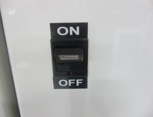
- Turn off the power to your rewind system and unplug it.
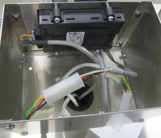
- Use a flathead screwdriver to open the enclosure.
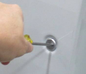
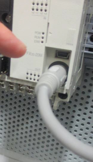
- Check the gray cable to make sure that it is plugged into the PLC and that it has not vibrated loose.
- Close and lock the enclosure and turn the power on to the rewind system.
- Turn the power on the touchscreen should be working. (If not proceed to the next section.)
CAUTION: BE SURE TO UNPLUG SYSTEM FROM POWER SOURCE.
- Turn off the power to your rewind system and unplug it.
- Remove HMI cover and back plate on pedestal enclosure
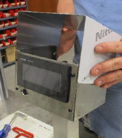
- Make sure all wires are connected and are not loose.
- Reconnect HMI cover and back plate on pedestal enclosure
- Reconnect system to power supply and turn on the system. The touchscreen should be working. If not contact Web Techniques for further troubleshooting.

- Details
- Troubleshooting and Guides

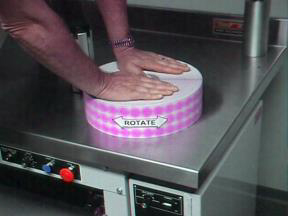
We recommend using an aerosol spray can of Pledge Cleaner with your rewind machine. When a machine is brand new, the stainless steel top is clean and has a “grain” that supports the roll of labels on millions of miniature points. After winding a few rolls, the high points in the stainless steel begin to smooth off and the valleys in the grain fill with residue from the sides of the roll. As the machine ages, the stainless becomes smoother and smoother and the rolls of material make contact with an even greater surface area of the table. Taking a few moments to clean the top with Pledge will restore lubricity to the stainless steel surface and result in looser rolls.
Tightness of a wound roll (created by web tension) is determined by the amount of braking applied on the unwind and by friction of the roll running against the table surface. When a roll of labels is wound too tightly, the adhesive will “bleed” from the edges of the label and the roll will become sticky and not unwind freely. Delicate webs (such as perforated labels) can break under high tension. It is possible for friction alone to create more web tension than is desired.
Prove to Yourself That It Works
Before cleaning the table top, lay a roll of labels on the table surface. While pressing downward, note the amount of force required to rotate the roll by hand. Then clean the table top with Pledge and repeat the process. You will note a dramatic reduction in the amount of force it takes to rotate the roll.
Why Not Silicone Spray?
Many people report using silicone spray to provide the same effect. Our experience with silicone spray is that it tends to build up and become sticky as it ages. When it is first applied and is still “wet,” silicone provides similar lubricity to Pledge. However, it does not hold up nearly as long. Furthermore, while the silicone surface may reduce friction between the roll and table top once the web is in motion, the static friction that must be overcome to get the roll moving is much higher than when pledge is used. The “wax” surface created by Pledge just simply works better.
Try it. We think you'll like it!
- Details
- Troubleshooting and Guides
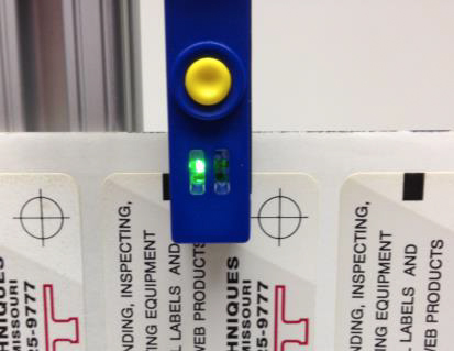
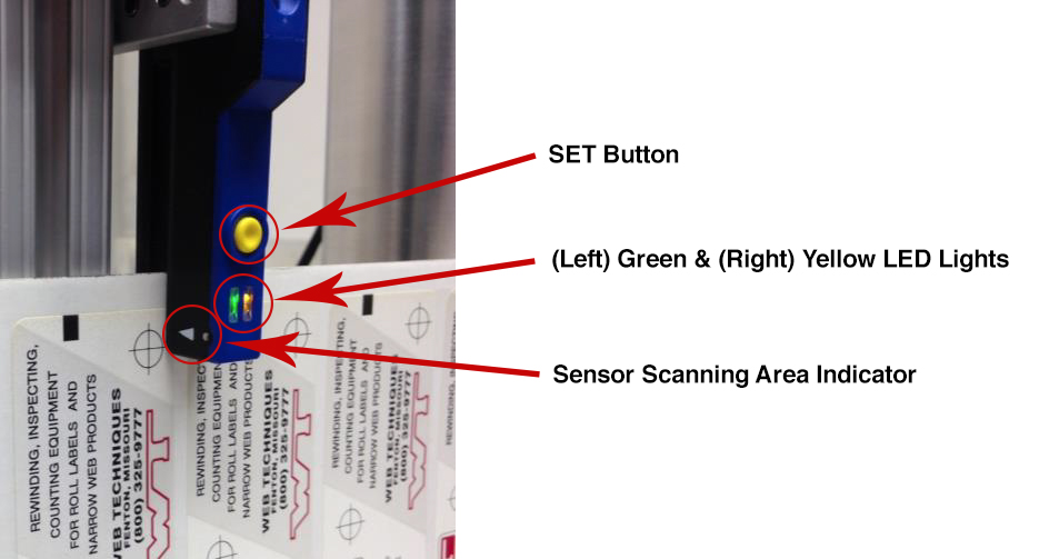
The DL1 sensor is an optoelectronic slot sensor that is used for detecting pressure sensitive labels on a liner that have a space between them. The scanner does not require any maintenance other than to periodically clean the optical sensor with a soft cloth and check that the electrical connections remain tight.
Training the DL-1 Gap Label Sensor
- Position a gap (it may be easier to remove a label while setting the DL1 sensor) in the sensing area of the DL1 gap sensor.
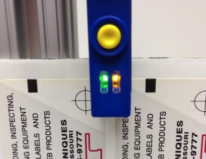
- Press and hold the yellow setting button on the sensor for three seconds while the sensor is trained over the gap or liner material to be counted/triggered until the OUT yellow LED blinks.
- Once the yellow SET button is released, the sensor has acquired the target material.
- Now position the label and liner/backing in the DL1’s sensing area briefly press the yellow SET button while the label and liner/backing are in the DL1’s sensing area. Three blinks of the green READY LED indicate successful training of the DL1 gap sensor.
Notes:
- In case of unsuccessful acquisition, the READY green LED blinks quickly. If this is the case, briefly press the yellow SET button to go back to Step 1 of the training procedure and follow the steps accordingly.
- If error persists, label-to-background contrast might be insufficient to obtain a correct acquisition result. Contact Web Techniques to determine if another Label Sensor may be needed for your application.
- Details
- Troubleshooting and Guides
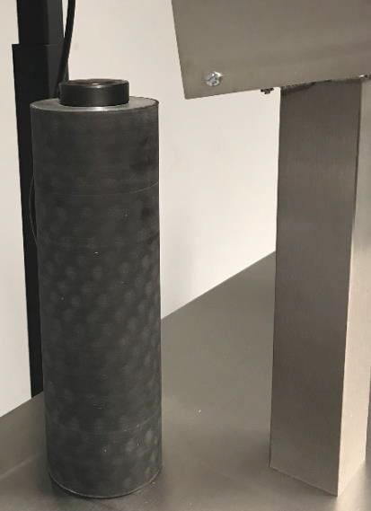
Panel mount Encoder Part Number: 77-9511-1. This encoder controls the Speed Set Point (speed knob on the front stinger of the WT-30)
DL Encoder 1000PPR Part Number: 80-6018. This encoder controls the Actual Speed (encoder drive roll)

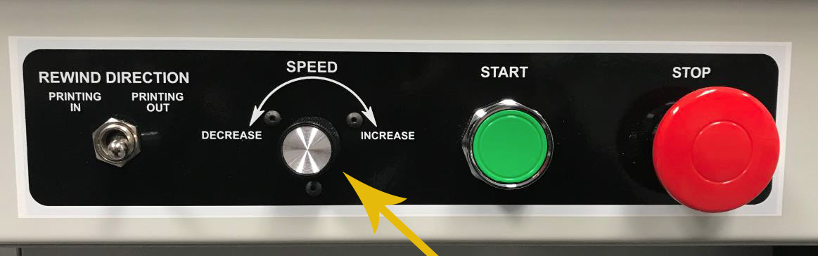
If you turn the speed knob and the Speed Set Point does NOT change, then you need a new Panel Mount Encoder. Especially if you can manually change the speed set point via the touchscreen.
- Details
- Troubleshooting and Guides
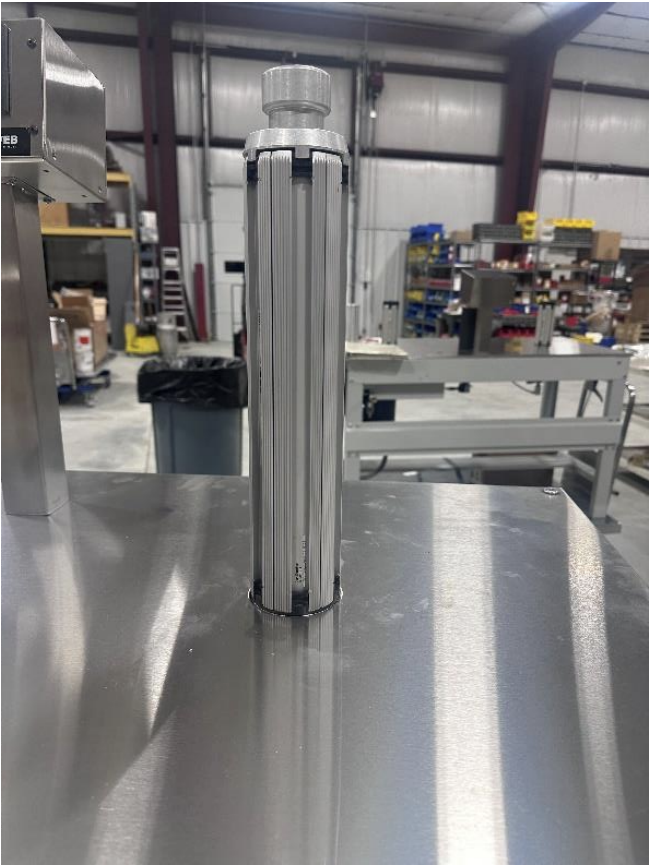
- Locate the roll pin near the top of the coreholder. Using a permanent black marker, draw a line directly from the roll pin hole, up to the top of the coreholder and approximately ¼" way over the top of the coreholder. This will allow for easy orientation of the stem and body when re-assembling the coreholder.
- Remove the roll pin and retain for reassembly. The figure below shows the roll pin of a 1" dia. Air coreholder being removed.
- (Preferred Method) Wrap the coreholder in a protective cloth and insert the body of the coreholder sideways into a vise. Tighten the vise against the body of the coreholder.
- Using a 3/8” dia. or smaller pin punch and hammer, tap the top center of the coreholder which will break the loctite seal between the coreholder stem and the body. Once the seal has been broken, continue tapping until the stem can be removed from the bottom of the coreholder. Note: Once the stem is removed from the body of the coreholder, the leaves will no longer be supported within the coreholder. Retain the leaves for re-assembly.
- Replace the defective bladder with the replacement bladder and secure onto stem using the nylon coated string provided with the kit.
- Carefully re-insert the stem and leaves into the body of the coreholder. Insert the stem so that the marker lines drawn in Step 1 are aligned. Using a wood block as a buffer between the lower stem post and the hammer, tap the wood block until the stem is tightly positioned inside the body of the coreholder. Re-insert the roll pin to secure.