COUNTING SYSTEM
The rewind machine incorporates a bi-directional dual preset counter. This permits the operator to set sepa- rate deceleration (Preset A) and stop (Preset B) points. The counter is driven by means of two magnetically operated reed switches located in the table top beneath the counter drive roll. A magnet in the lower end of the counter drive roll operates the reed switches. The combined signals from each reed switch allow the counter to automatically count up or down depending on the direction of rotation of the counter drive roll. This is primarily used when pulling defective material backwards off the rewind roll. Be sure the web is held against the counter drive roll when it is pulled backwards.
PROGRAMMING DECELERATION AND STOP POINTS
To set the final count, press the PRE B button on the counter once. In approximately two seconds the current value will be displayed. To change the value, simply press the button under the digit that you wish to change. Each time the button is pressed, the digit will increment by one. When the desired value has been set, push ENTER once to store the value into memory. To set the count at which you wish the machine to go into the deceleration mode, push PRE A and follow the same procedure as described above. If you do not wish to have a deceleration period, simply set the final count Preset B as normal and set Preset A to any number larger than Preset B.
While it is possible for the counter to become unlocked (possibly due to line noise, electrical storms, etc.), it is important to note that this will disable the counter from performing as it should. In order to correct the situation, the counter will need to be re-programmed. For your convenience, we have provided re- programming instructions located in the final section of this manual in the event that this occurs
DETERMINING PRESET B (STOP POINT)
The counter registers one count per ten inches of web travel when using the standard ten-inch circumference counter drive roll. This makes it easy to calculate the appropriate number to enter into the counter in order to wind a roll of a given number of labels. The number is calculated as follows:
𝐂𝐨𝐮𝐧𝐭 = (𝑵𝒐. 𝒐𝒇 𝒅𝒆𝒔𝒊𝒓𝒆𝒅 𝒍𝒂𝒃𝒆𝒍𝒔)(𝒓𝒆𝒑𝒆𝒂𝒕 𝒍𝒆𝒏𝒈𝒕𝒉)/𝟏𝟎
EXAMPLE: To wind a roll of 1000 labels of 3 inch repeat length, the number 300 would be entered as the final count (Preset B).
𝐂𝐨𝐮𝐧𝐭 = (𝟏𝟎𝟎𝟎)(𝟑)/𝟏𝟎 = 𝟑𝟎𝟎
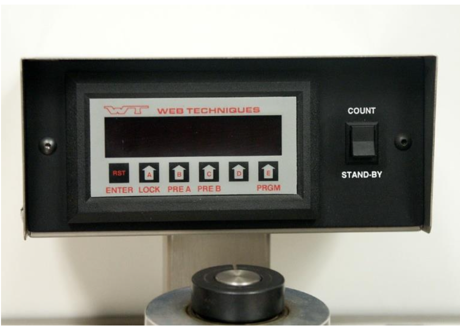
Figure 2 Counter Package
DETERMINING PRESET A (DECELERATION COUNT SETTING)
The point at which deceleration should begin depends on many factors (rewind speed, finished roll diameter, etc.). Therefore you probably will need to test your de- celeration count setting each time you rewind a new type of label. The desired technique is to have the ma- chine stop shortly after it decelerates fully and has sta- bilized at the lower speed. For the first attempt try a setting that is fifty counts less than the final count. This means that the counter will begin to decelerate the machine 50 counts before the end of the roll. EXAMPLE: If the final count (Preset B) is 300, then the deceleration count (Preset A) should be set at 250.
AUTOMATIC RESET
After winding a roll (and reaching the final preset num- ber), the counter will reset to zero automatically when the start pushbutton is pressed to start a new roll. This is the only time automatic resetting can occur. Counting will proceed normally each time the machine is stopped and started (without resetting) until Preset B has been reached. You may reset the counter to zero at any time by pushing the “RST” button on the counter.
ELECTRICAL CONTROL ADJUSTMENTS
The following list of settings has been pre-adjusted by Web Techniques, Inc. to cover most applications. If these settings are not optimal for your requirements, adjustments may be made with discretion. These set- tings are located on the printed circuit board closest to the terminal blocks on the motor control. The motor control is located inside the control cabinet.
MINIMUM SPEED
If a higher than zero minimum speed is desired, readjust the minimum speed by turning the main speed control knob on the front of the machine to zero setting (full counterclockwise position). Then adjust the trim poten- tiometer marked MIN to the desired setting.
DECELERATION RATE
If your labels become loose during the deceleration period with the web tension set at the necessary level, you should increase the deceleration rate by turning the trim potentiometer marked DECEL clockwise. If you feel that the deceleration period is too long, turn the decel- eration trim potentiometer counterclockwise to reduce the deceleration rate.
ACCELERATION RATE
Turning the trim potentiometer marked ACCEL clock- wise increases the amount of time required for the mo- tor to reach full speed. The setting should be such that the web does not break when the motor is started.
PROCEDURE FOR RE- PROGRAMMING KEP MC2A9 COUNTERS
UNLOCKING THE COUNTER
- Press LOCK. The display will show “CodE” for a few seconds.
- When “CodE” disappears, enter the code 13579 and press ENTER.
- The counter will then show “un LoC” for a few se- conds. You are now ready to reprogram the counter.
SETTING SCALE FACTORS
- Press PRGM.
- When “FACtor” appears, press ENTER.
- When “dP F A” appears, press PRGM. Then press ENTER.
- Set “dP F A” to 1 if it is not already set to 1 and press ENTER.
- When “dP F b” appears, press PRGM. Then press ENTER.
- Set “dP F b” to 1 if it is not already set to 1 and press ENTER.
- Press ENTER again.
SETTING COUNT MODE
- Press PRGM twice.
- When “Count” appears, press ENTER. Then (if necessary) press PRGM until “rSt 0” appears.
- Press ENTER.
- When “dP LoC” appears, press PRGM. Then press ENTER.
- If necessary, press PRGM until “A nEtb” appears.
- Press ENTER.
- If necessary, press PRGM until “ASub b” appears.
- Press ENTER.
- If necessary, press PRGM until “Hi CPS” appears.
- Press ENTER.
SETTING THE RELAY OPERATION
- Press PRGM 4 times (until “rELAY” appears).
- Press ENTER.
- Set “A XX.X” to “A 00.0” and press Enter.
- Set “b XX.X” to “b 00.0” and press Enter.
SETTING THE COUNTER LOCK CODE
- Press PRGM 3 times (until “LoC” appears).
- Press ENTER.
- If necessary, press PRGM until “LC Pr9” appears.
- Press ENTER.
- The display will show “CodE” for a few seconds.
- When “CodE” disappears, enter the code 13579 and press ENTER.
LOCKING THE COUNTER
- Press LOCK. The display will show “CodE” for a few seconds.
- When “CodE” disappears, enter the code 13579 and press ENTER.
- To verify that the counter is locked, press the PRGM key. The “LoC” message should appear on the counter.