STEP 1: ENSURE SYSTEM MAIN POWER SWITCH IS IN THE OFF POSITION AND/OR UNPLUGGED BEFORE
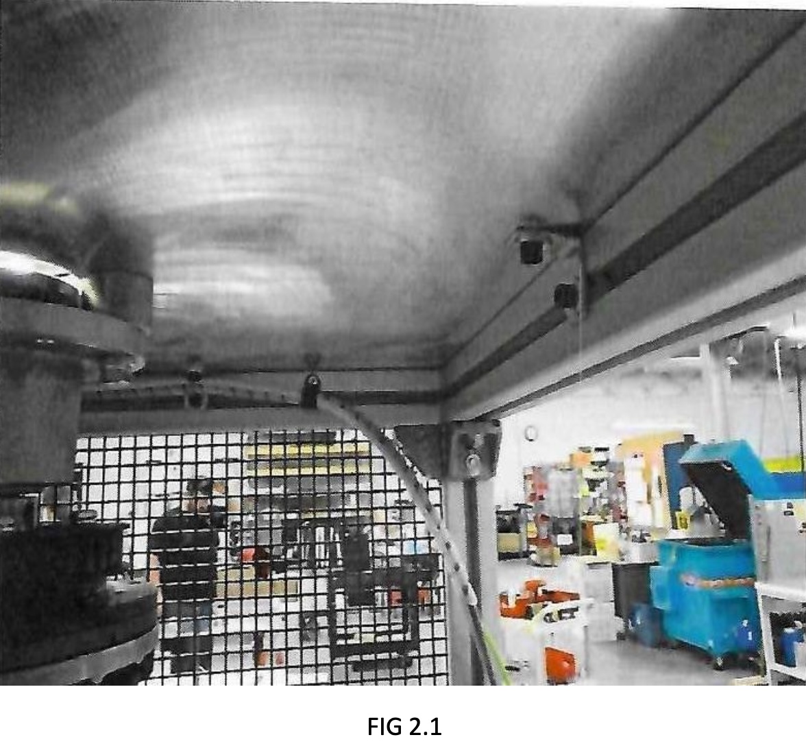
STEP 2: SECURING TOP TO FRAME
2-A) Secure angle brackets to top(FIG. 2.1). Use (5) ¼-20 X 5/8” SHCS (C1M5/6302505) and ¼” washer (C1C1/6612500). Hand tighten SHCS to top to make sure top is in correct position. After all are hand tightened, tighten to frame first, then top(FIG. 2.1).
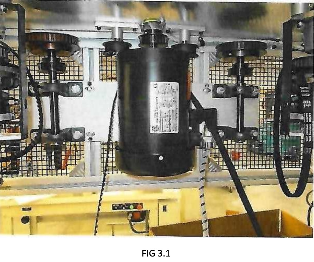
STEP 3: ADUSTING PULLEYS AND BELTS
3-A) Place ½” timing belt (C2 side/90-9318) over motor (FIG 3.1).
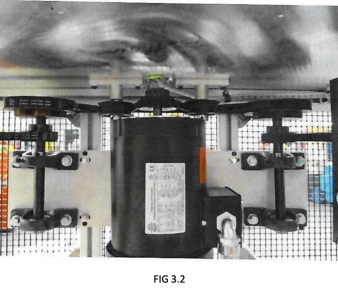
3-B) Place belts on pulleys (FIG 3.2).
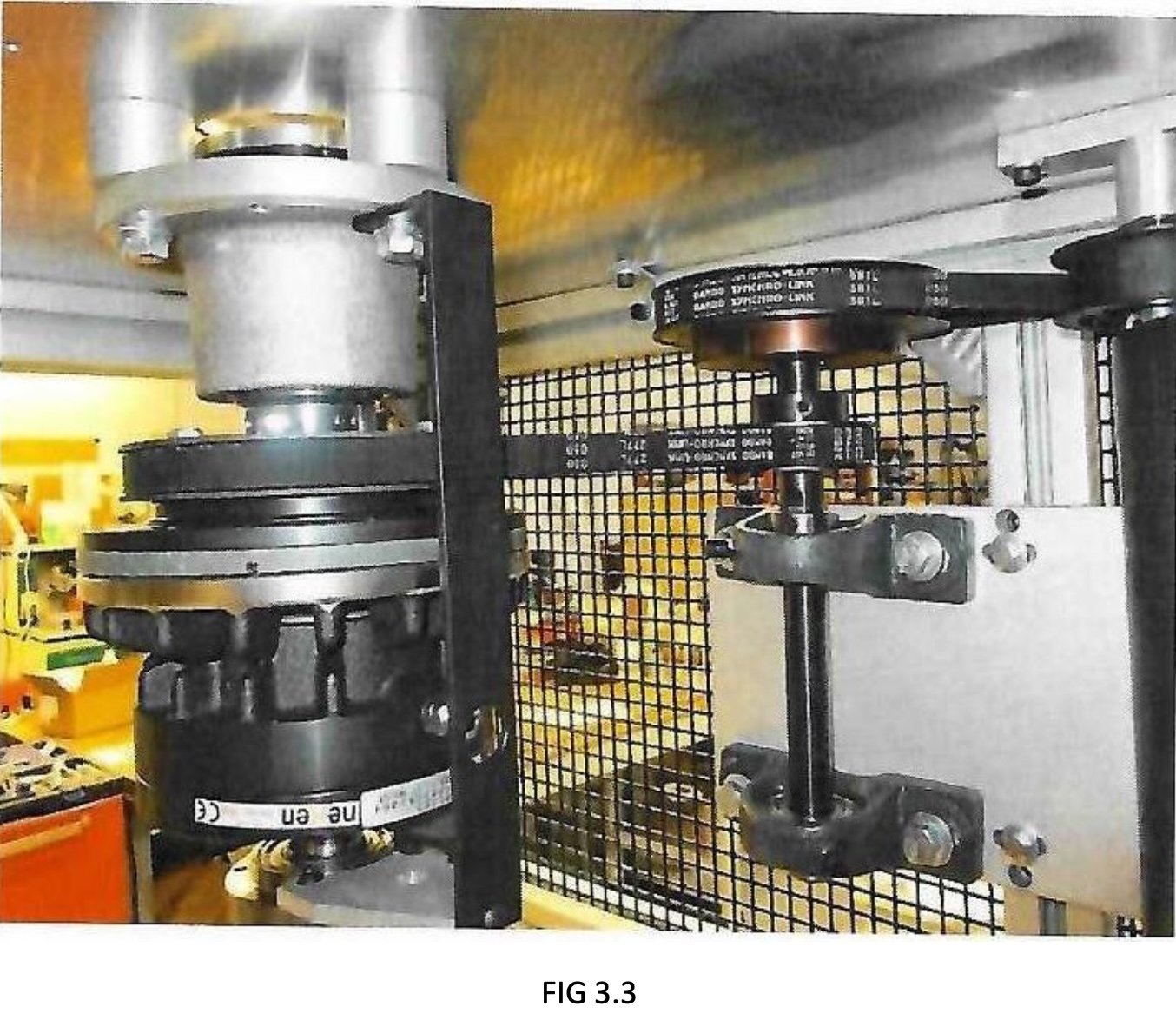
3-C) Adjust small belts on shaft assembly to where belts have approximately ½” give, then tightening bolts on pillow bearing blocks (FIG 3.3).
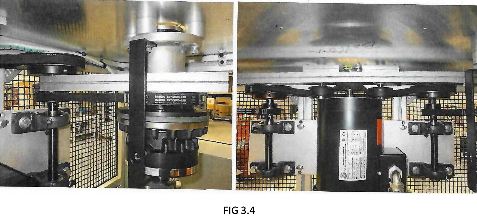
3-D) Use straight edge to make sure pulleys are even with each other and pulleys are parallel to top.
Double check screws on shaft assembly are tight (FIG 3.4).
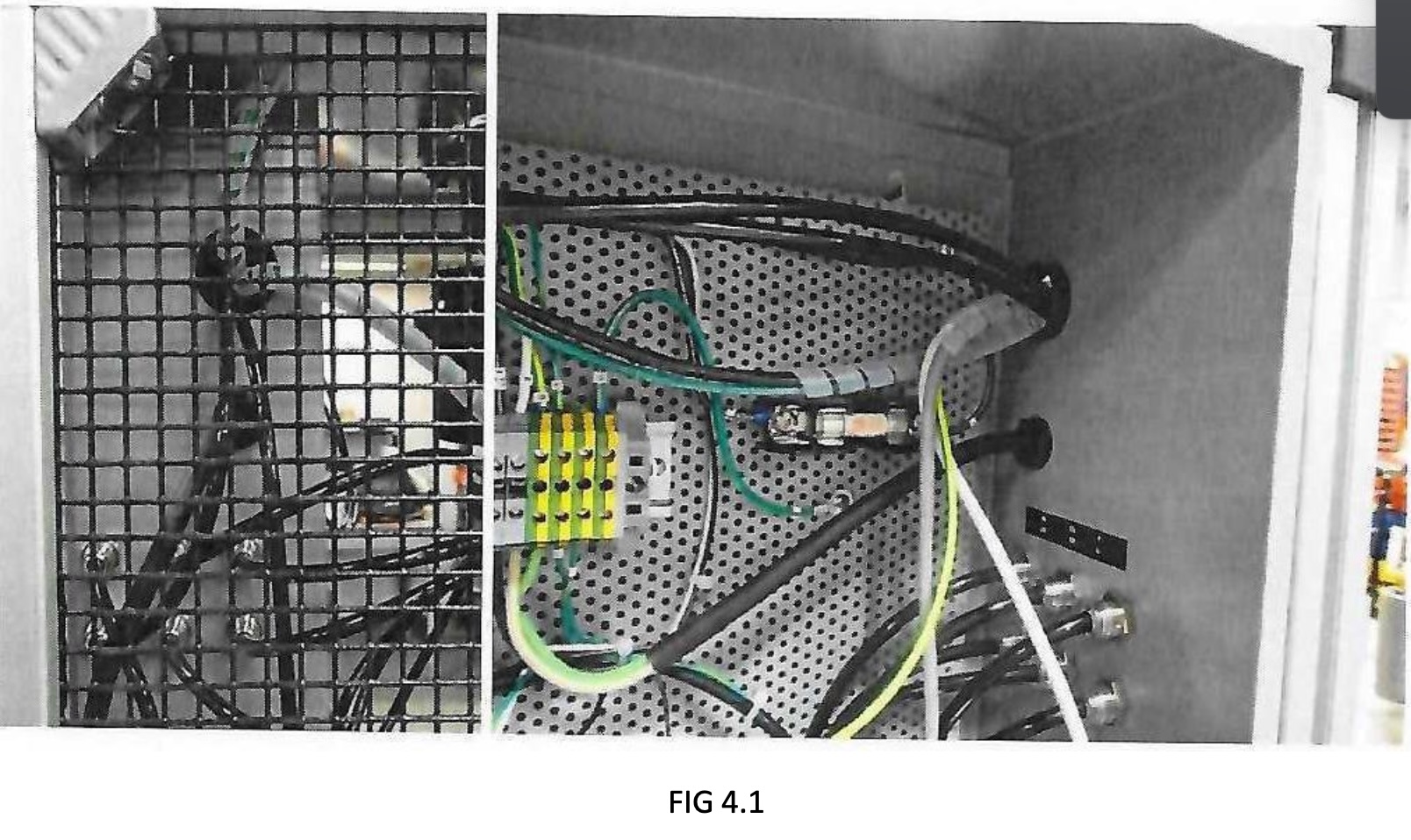
STEP 4: POSITIONING ENCLOSURE AND FEEDING CABLES INTO ENCLOSURE
4-A) Feed COM cable, scanner cable, ground wire, and motor power cables through top hole of enclosure (FIG 4.1)