System Drive Belt Removal and Installation Procedure.
NOTE: BE SURE POWER IS OFF AND SYSTEM IS UPLUGGED FROM POWER SOURCE.
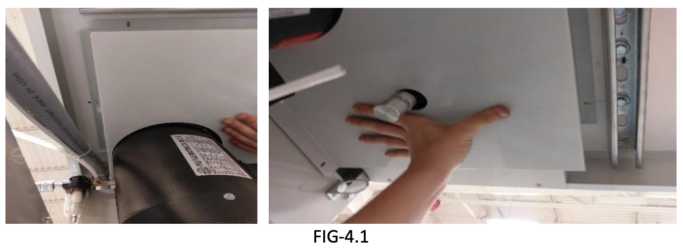
STEP 1: Remove belt guard from bottom of WT-26 system by removing (3) 8-32 x 1/2" screws (FIG-1.1) on the bottom of the systems top and (2) STPH #8 x 3/4” screws from the motor mounting plate (FIG-1.2).
CAUTION: WHEN REMOVING BELT GUARD BE SURE TO HOLD IN PLACE WITH HAND SO THAT IT DOES NOT FALL.
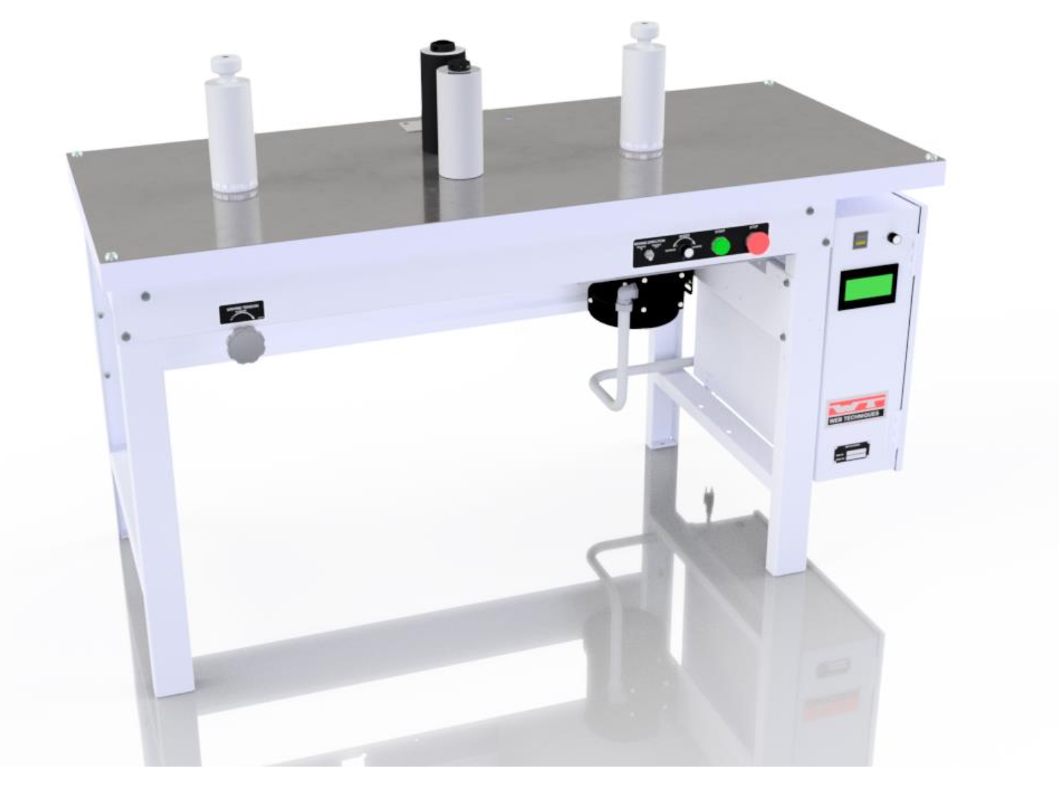
STEP 2: Loosen motor mounts and push motor towards larger pulley. If belt will not come off, motor will need to be removed completely. To remove motor, loosen and remove all four nuts and lock washers from mounting studs.
CAUTION: MOTOR IS HEAVY DO NOT DROP WHILE REMOVING FROM STUDS.
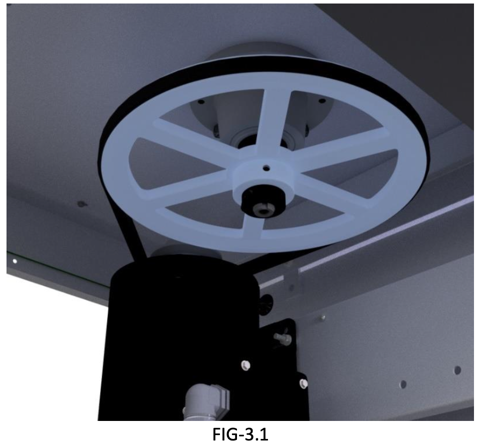
STEP 3: Place belt around both pulleys and place motor back on motor mounting studs (FIG-3.1). Screw nuts back on studs but do not tighten down with appropriate hardware. Push motor away from big pulley to tighten belt then tighten motor in place.
CAUTION: DO NOT OVER TIGHTEN BELT, BELT SHOULD HAVE A 1⁄2” OF PLAY WHEN PRESSING ON THE MIDDLE OF BELT.
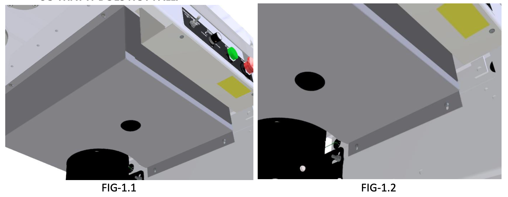
STEP 4: Install the belt guard (19-1240-1) using (3) 8-32 x1/2” hex-washer head screws, and (2) pan head screws. Use the hex-washer head screws for wooden holes and pan head screws for holes into frame (FIG-4.1).